
Page 308 - Electrician - TT (Volume 1)
P. 308
ELECTRICIAN - CITS
On some multimeters, two switches are used, one to select a function, and the other the range. Some multimeters
do not have switches for this purpose; instead, they have separate jacks for each function and range.
Batteries/cells fixed inside the meter case provide the power supply for the resistance measurement.
The meter movement is that of the moving coil system as used in DC ammeters and voltmeters.
Rectifiers are provided inside the meter to convert AC to DC in the AC measurement circuit.
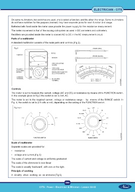
Parts of a multimeter
A standard multimeter consists of the main parts and controls (Fig 2).
Fig 2
Controls
The meter is set to measure the current, voltage (AC and DC) or resistance by means of the FUNCTION switch.
In the example given in Fig 3 the switch is set to mA, AC.
The meter is set to the required current, voltage or resistance range - by means of the RANGE switch. In
Fig 4, the switch is set to 2.5 volts or mA, depending on the setting of the FUNCTION switch.
Fig 3 & 4
Scale of multimeter
Separate scales are provided for:
• resistance
• voltage and current.(Fig 5)
The scale of current and voltage is uniformly graduated.
The scale of the ohmmeter is non-linear.
The scale is usually ‘backward’, with zero at the right.
Principle of working
A circuitry when working as an ammeter.(Fig 6)
295
CITS : Power - Electrician & Wireman - Lesson 50-53 CITS : Power - Electrician & Wireman - Lesson 50-53