
Page 336 - Electrician - TT (Volume 2)
P. 336
ELECTRICIAN - CITS
for protecting generators from faults to ground. Differential protection of busbars in substations uses one CT for
each incoming line. All incoming currents are added up and compared to the sum of all out going currents.
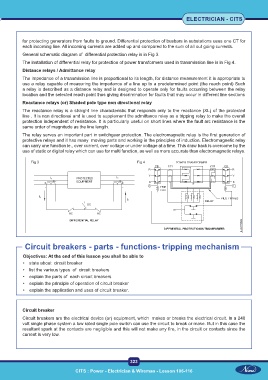
General schematic diagram of differential protection relay is in Fig 3.
The installation of differential relay for protection of power transformers used in transmission line is in Fig 4.
Distance relays / Admittance relay
The impedance of a transmission line is proportional to its length, for distance measurement it is appropriate to
use a relay capable of measuring the impedance of a line up to a predetermined point (the reach point) Such
a relay is described as a distance relay and is designed to operate only for faults occurring between the relay
location and the selected reach point thus giving discrimination for faults that may occur in different line sections
Reactance relays (or) Shaded pole type non directional relay
The reactance relay is a straight line characteristic that responds only to the reactance (XL) of the protected
line . It is non directional and is used to supplement the admittance relay as a tripping relay to make the overall
protection independent of resistance. It is particularly useful on short lines where the fault arc resistance is the
same order of magnitude as the line length.
The relay serves an important part in switchgear protection. The electromagnetic relay is the first generation of
protective relays and it has many moving parts and working in the principles of induction. Electromagnetic relay
can carry one function ie., over current, over voltage or under voltage at a time. This draw back is overcome by the
use of static or digital relay which can use for multi function, as well as more accurate than electromagnetic relays.
Fig 3 Fig 4
Circuit breakers - parts - functions- tripping mechanism
Objectives: At the end of this lesson you shall be able to
• state about circuit breaker
• list the various types of circuit breakers
• explain the parts of each circuit breakers
• explain the principle of operation of circuit breaker
• explain the application and uses of circuit breaker.
Circuit breaker
Circuit breakers are the electrical device (or) equipment, which makes or breaks the electrical circuit. In a 240
volt single phase system a low rated single pole switch can use the circuit to break or make. But in this case the
resultant spark at the contacts are negligible and this will not make any fire, in the circuit or contacts since the
current is very low.
323
CITS : Power - Electrician & Wireman - Lesson 106-116 CITS : Power - Electrician & Wireman - Lesson 106-116